【第4回】日本語版SwiftUIチュートリアル【図形の描画】

日本語版SwiftUIチュートリアル

本チュートリアルは,Appleが掲載している公式のSwiftUIチュートリアルを「日本語で」そして「詳細に」解説し直すことを目的とした記事です.
この手の記事は,他にも似たようなものがありますが,全てを網羅しているわけではなく,部分的に解説している記事が多数です.
そこで,SwiftUIを使ってアプリ開発をしたい方々のために,そして勉強している自分自身のために,日本語版SwiftUIチュートリアルの完全版を書きます.
なお,本記事の難易度としては,初級者も見様見真似で作れるようにはなっていますが,それでは物足りないという中級者のために,細かい文法的な解説も随所に入れていこうと思います.
注意として,本記事はSwiftの言語解説はあまり含まないので,以下の記事を別タブで開いておいて,分からなければ逐一確認してみると良いと思います.
ちなみに出来上がるアプリは,上図に示すような観光地アプリです.
各観光地の位置情報を確認したり,その観光地をお気に入りに追加したりできるアプリを目指します.
第1回は????
第4回:図形の描画
第4回では,前回作成したアプリからは少し離れ,SwiftUIでの図形描画を使ったバッジビューの解説を行っていきます.
といっても,今回作ったバッジは最終的にはひとつのアプリケーションに統合されるのでご安心ください.
今回作成するバッジは以下のようなものです.
Step 1. バッジを仮で定義する
いきなり複雑なバッジを作成するのは困難ですが,まずは大枠を作って簡単なバッジの作り方を学びましょう!
まずは新たに「Badge.swift」をプロジェクトルートディレクトリに作成します.
1 2 3 4 5 6 7 8 9 10 11 12 13 | import SwiftUI struct Badge: View { var body: some View { Text("Hello, World!") } } struct Badge_Previews: PreviewProvider { static var previews: some View { Badge() } } |
そうしたら,早速簡単な図形を使ってバッジを作ります.
通常,SwiftUIの図形描画は,輪郭情報の Path 型 (構造体) を使用して行います.
1 2 3 4 5 6 7 | struct Badge: View { var body: some View { Path { path in } } } |
今はまだ何も書いていませんが,この Path { } の引数に図形の輪郭情報を定義していく形になります.
例えば直接,予め用意されている図形を追加することもできます.
1 2 3 4 5 6 7 8 9 10 11 | struct Badge: View { var body: some View { Path { path in path.addRect(CGRect( x: 50, y: 50, width: 100, height: 200)) } } } |

または,自分で頂点座標を定めて結び,それを塗りつぶす,といったことも可能です.
1 2 3 4 5 6 7 8 9 10 11 12 | struct Badge: View { var body: some View { Path { path in path.addLines([ CGPoint(x: 100, y: 100), // 左上 CGPoint(x: 200, y: 200), // 右下 CGPoint(x: 200, y: 100), // 右上 CGPoint(x: 100, y: 100), // 左上に戻る ]) }.stroke() } } |
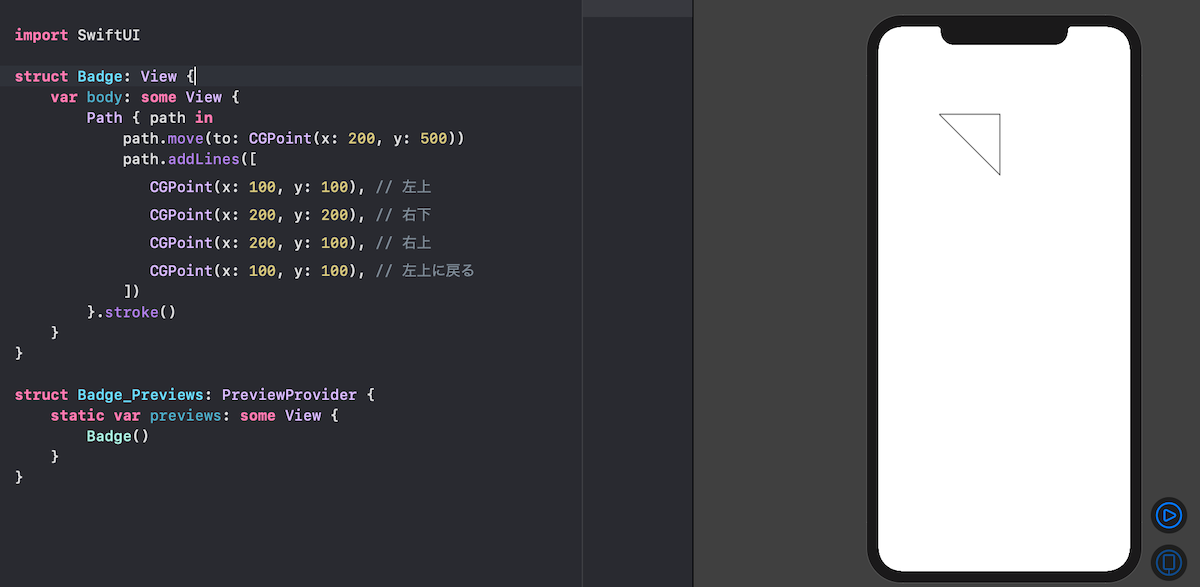
1 2 3 4 5 6 7 8 9 10 11 12 | struct Badge: View { var body: some View { Path { path in path.addLines([ CGPoint(x: 100, y: 100), // 左上 CGPoint(x: 200, y: 200), // 右下 CGPoint(x: 200, y: 100), // 右上 CGPoint(x: 100, y: 100), // 左上に戻る ]) }.fill(Color.green) } } |

次の内容を理解しやすくするために,もう少しだけ図形描画の基礎を学びましょう.
先ほどまでは,座標を追加していく方法をとりましたが,以下のような線の引き方も可能です.
1 2 3 4 5 6 7 8 9 10 11 | struct Badge: View { var body: some View { Path { path in path.move(to: CGPoint(x: 100, y: 100)) path.addLine(to: CGPoint(x: 200, y: 200)) }.stroke() } } |

move(to: ) で描画の始点座標を最初に決め, addLine(to: ) で終点座標を決めて線を引く方法です.
これを使えば,
1 2 3 4 5 6 7 8 9 10 11 12 13 14 | struct Badge: View { var body: some View { Path { path in path.move(to: CGPoint(x: 100, y: 100)) path.addLine(to: CGPoint(x: 200, y: 200)) path.move(to: CGPoint(x: 300, y: 100)) path.addLine(to: CGPoint(x: 250, y: 200)) }.stroke() } } |
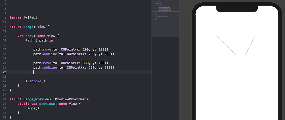
のような描画も可能です.
そしてもう一つ重要な描画方法として以下のようなものがあります.
1 2 3 4 5 6 7 8 9 10 11 12 13 14 15 16 17 18 19 | struct Badge: View { var body: some View { Path { path in path.move(to: CGPoint(x: 100, y: 100)) path.addLine(to: CGPoint(x: 200, y: 200)) path.move(to: CGPoint(x: 300, y: 100)) path.addLine(to: CGPoint(x: 250, y: 200)) path.addQuadCurve( to: CGPoint(x: 200, y: 200), control: CGPoint(x: 230, y: 230) ) }.stroke() } } |
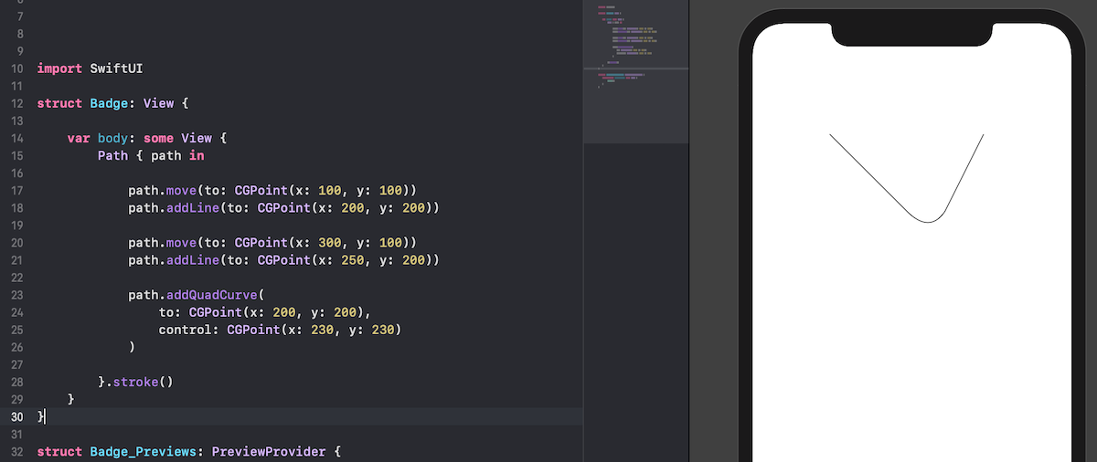
このようなカーブの描画です.
上記コードは以下のようなイメージです.
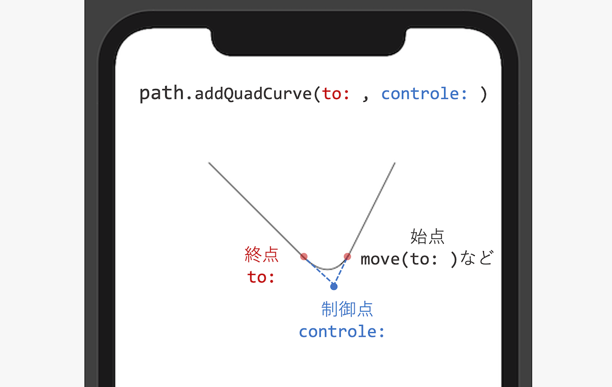
始点は move(to: ) に限らず,最後に移動し終えた座標が,それにあたります.
今回は最後の path.addLine(to: CGPoint(x: 250, y: 200)) で移動した点が,カーブの始点になりますね.
これらを踏まえた上で,本題に移ります.
Step 2. バッジ背景で使う六角形を定義する
さて,背景で使用する六角形を決めるパラメータを管理する構造体を定義しましょう.
「HexagonParameters.swift」を新たにプロジェクトルートディレクトリに作成します.
1 2 3 4 5 | import SwiftUI struct HexagonParameters{ } |
実際,公式チュートリアルでは定義の説明は皆無ですが,先ほどの話を踏まえて少しだけ解説を入れて実装してみます.
この構造体では,各頂点座標を管理するので, points というプロパティを持たせてあげます.
1 2 3 4 5 6 7 8 9 | import SwiftUI struct HexagonParameters{ static let points = [ ] } |
ここで,注意として今回描画しようとしている六角形はコーナーが角張ったようなものではなく,丸みを帯びた六角形を描画しようとしています.
なので,先ほど出てきた制御点と終点もパラメータとして管理を行います.
そこでそれらを一つの構造体として管理してしまいましょう.
1 2 3 4 5 6 7 8 9 | struct HexagonParameters{ struct Segment { let useWidth: (CGFloat, CGFloat, CGFloat) let xFactors: (CGFloat, CGFloat, CGFloat) let useHeight: (CGFloat, CGFloat, CGFloat) let yFactors: (CGFloat, CGFloat, CGFloat) } ... } |
これだけを見ると,それぞれのプロパティが何を示しているのかわかりにくいですね.
使い方としては,図形の大きさとして width と height という定数をもとに描画することを考えています.
それらに対してその定数を使うか否か ( useXxx ) ,そしてどのくらいの係数 ( xFactor ) で描画するかをこれで管理しようという考えです.
また,各タプルのインデックスはそれぞれ, ("始点", "終点", "制御点") として扱うことにします.
そうしたら角頂点の関係を定義していきます.
1 2 3 4 5 6 7 8 9 10 11 12 13 14 15 16 17 18 19 20 21 22 23 24 25 26 27 28 29 30 31 32 33 34 35 36 37 38 39 40 41 42 43 44 45 46 47 48 49 | struct HexagonParameters{ struct Segment { let useWidth: (CGFloat, CGFloat, CGFloat) let xFactors: (CGFloat, CGFloat, CGFloat) let useHeight: (CGFloat, CGFloat, CGFloat) let yFactors: (CGFloat, CGFloat, CGFloat) } static let adjustment: CGFloat = 0.085 static let points = [ Segment( useWidth: (1.00, 1.00, 1.00), xFactors: (0.60, 0.40, 0.50), useHeight: (1.00, 1.00, 0.00), yFactors: (0.05, 0.05, 0.00) ), Segment( useWidth: (1.00, 1.00, 0.00), xFactors: (0.05, 0.00, 0.00), useHeight: (1.00, 1.00, 1.00), yFactors: (0.20 + adjustment, 0.30 + adjustment, 0.25 + adjustment) ), Segment( useWidth: (1.00, 1.00, 0.00), xFactors: (0.00, 0.05, 0.00), useHeight: (1.00, 1.00, 1.00), yFactors: (0.70 - adjustment, 0.80 - adjustment, 0.75 - adjustment) ), Segment( useWidth: (1.00, 1.00, 1.00), xFactors: (0.40, 0.60, 0.50), useHeight: (1.00, 1.00, 1.00), yFactors: (0.95, 0.95, 1.00) ), Segment( useWidth: (1.00, 1.00, 1.00), xFactors: (0.95, 1.00, 1.00), useHeight: (1.00, 1.00, 1.00), yFactors: (0.80 - adjustment, 0.70 - adjustment, 0.75 - adjustment) ), Segment( useWidth: (1.00, 1.00, 1.00), xFactors: (1.00, 0.95, 1.00), useHeight: (1.00, 1.00, 1.00), yFactors: (0.30 + adjustment, 0.20 + adjustment, 0.25 + adjustment) ) ] } |
いきなり,コードが増えましたがここはコピペで構いません.
この後,これを呼び出しながら様子を理解していきましょう.
Step 3. Badgeで背景を描画してみる
そうしたら,先ほどの六角形を背景として描画していきましょう.
1 2 3 4 5 6 7 8 9 10 11 12 13 14 15 16 17 18 19 20 21 22 23 24 25 26 27 28 29 30 31 32 33 34 35 36 | struct Badge: View { var body: some View { Path { path in let width: CGFloat = 100.0 let height = width path.move( to: CGPoint( x: width * 0.95, y: height * (0.20 + HexagonParameters.adjustment) ) ) HexagonParameters.points.forEach { path.addLine( to: .init( x: width * $0.useWidth.0 * $0.xFactors.0, y: height * $0.useHeight.0 * $0.yFactors.0 ) ) path.addQuadCurve( to: .init( x: width * $0.useWidth.1 * $0.xFactors.1, y: height * $0.useHeight.1 * $0.yFactors.1 ), control: .init( x: width * $0.useWidth.2 * $0.xFactors.2, y: height * $0.useHeight.2 * $0.yFactors.2 ) ) } }.stroke() } } |
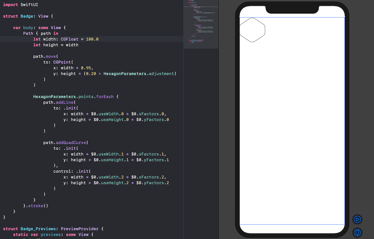
うまく描画できていそうです!
ここで, HexagonParameters.points.forEach { } はリストに対して各要素をクロージャの引数として処理を行うことができる関数です.
今回は引数名は指定していないので, $0 で代用できます.
また,タプルのインデックスをしていしたアクセスの仕方も,コードを見れば分かるかと思います.
クロージャの中でやっていることは,「線を引く」→「曲線を引く」の繰り返しですね.
このとき,線を引けば今見ている座標もそれに伴い移動するので, move(to: ) も最初だけです.
( move(to: )の座標で定数が使われているのが少し気持ち悪いですが,これは仕方がないのでスルーします)
さて,今は左上に寄った六角形が描画されていますが,これを画面全体を使った大きなサイズで描画をしたいと考えています.
こういった時は, GeometryReader { } という構造体が利用できます.
使い方はコードを実際に見てみましょう.
1 2 3 4 5 6 7 8 9 10 11 12 13 14 15 16 17 18 19 20 21 22 23 24 25 26 27 28 29 30 31 32 33 34 35 36 37 38 39 | struct Badge: View { var body: some View { GeometryReader{ geometry in Path { path in let width: CGFloat = min(geometry.size.width, geometry.size.height) let height = width path.move( to: CGPoint( x: width * 0.95, y: height * (0.20 + HexagonParameters.adjustment) ) ) HexagonParameters.points.forEach { path.addLine( to: .init( x: width * $0.useWidth.0 * $0.xFactors.0, y: height * $0.useHeight.0 * $0.yFactors.0 ) ) path.addQuadCurve( to: .init( x: width * $0.useWidth.1 * $0.xFactors.1, y: height * $0.useHeight.1 * $0.yFactors.1 ), control: .init( x: width * $0.useWidth.2 * $0.xFactors.2, y: height * $0.useHeight.2 * $0.yFactors.2 ) ) } }.stroke() } } } |
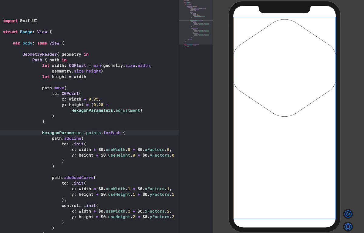
このように,親ビューのサイズや中心座標などを簡単に扱うことができるのが, GeometryReader { } です.
今回は,幅をビュー縦横サイズのうち,小さい方に指定しています.
さてもう少しデザインを整えていきましょう.
まずはx軸に対して余白を取ります.
1 2 3 4 5 6 7 8 9 10 11 12 13 14 15 16 17 18 19 20 21 22 23 24 25 26 27 28 29 30 31 32 33 34 35 36 37 38 39 40 41 42 43 | struct Badge: View { var body: some View { GeometryReader{ geometry in Path { path in var width: CGFloat = min(geometry.size.width, geometry.size.height) let height = width let xScale: CGFloat = 0.832 let xOffset = (width * (1.0 - xScale)) / 2.0 width *= xScale path.move( to: CGPoint( x: xOffset + width * 0.95, y: height * (0.20 + HexagonParameters.adjustment) ) ) HexagonParameters.points.forEach { path.addLine( to: .init( x: xOffset + width * $0.useWidth.0 * $0.xFactors.0, y: height * $0.useHeight.0 * $0.yFactors.0 ) ) path.addQuadCurve( to: .init( x: xOffset + width * $0.useWidth.1 * $0.xFactors.1, y: height * $0.useHeight.1 * $0.yFactors.1 ), control: .init( x: xOffset + width * $0.useWidth.2 * $0.xFactors.2, y: height * $0.useHeight.2 * $0.yFactors.2 ) ) } }.stroke() } } } |
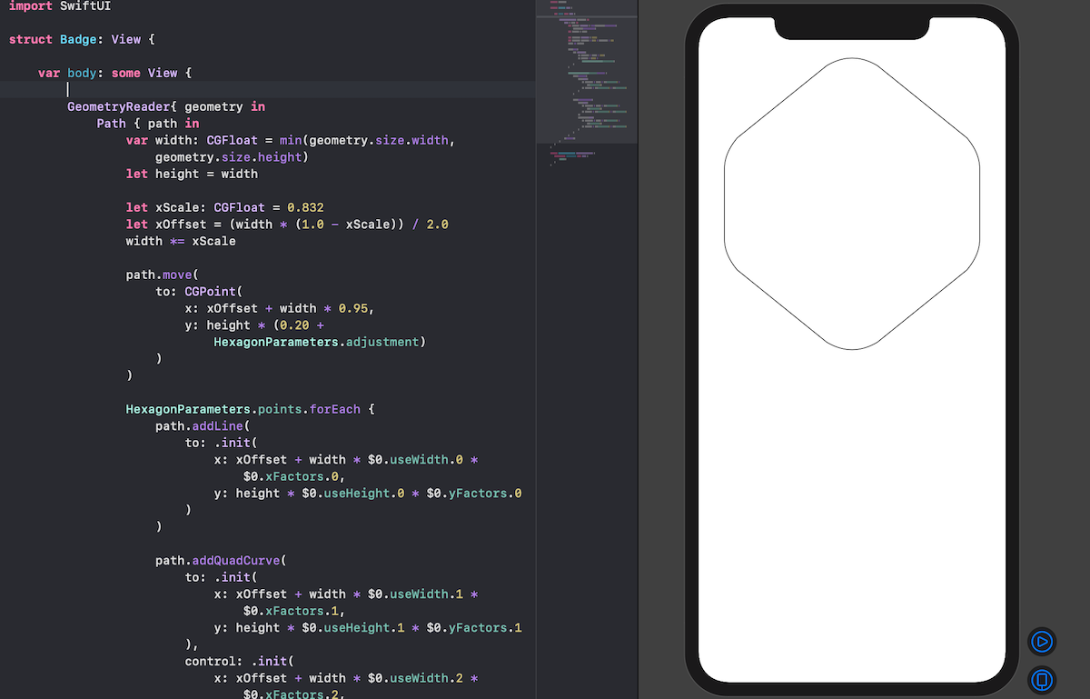
グラデーションカラーで塗りつぶしてみましょう.
1 2 3 4 5 6 7 8 9 10 11 12 13 14 15 16 17 18 19 20 21 22 23 24 25 26 27 28 29 30 31 32 33 34 35 36 37 38 39 40 41 42 43 44 45 46 47 48 49 | struct Badge: View { var body: some View { GeometryReader{ geometry in Path { path in var width: CGFloat = min(geometry.size.width, geometry.size.height) let height = width let xScale: CGFloat = 0.832 let xOffset = (width * (1.0 - xScale)) / 2.0 width *= xScale path.move( to: CGPoint( x: xOffset + width * 0.95, y: height * (0.20 + HexagonParameters.adjustment) ) ) HexagonParameters.points.forEach { path.addLine( to: .init( x: xOffset + width * $0.useWidth.0 * $0.xFactors.0, y: height * $0.useHeight.0 * $0.yFactors.0 ) ) path.addQuadCurve( to: .init( x: xOffset + width * $0.useWidth.1 * $0.xFactors.1, y: height * $0.useHeight.1 * $0.yFactors.1 ), control: .init( x: xOffset + width * $0.useWidth.2 * $0.xFactors.2, y: height * $0.useHeight.2 * $0.yFactors.2 ) ) } }.fill(LinearGradient( gradient: .init(colors: [Self.gradientStart, Self.gradientEnd]), startPoint: .init(x: 0.5, y: 0), endPoint: .init(x: 0.5, y: 0.6) )) } } static let gradientStart = Color(red: 239.0 / 255, green: 120.0 / 255, blue: 221.0 / 255) static let gradientEnd = Color(red: 239.0 / 255, green: 172.0 / 255, blue: 120.0 / 255) } |
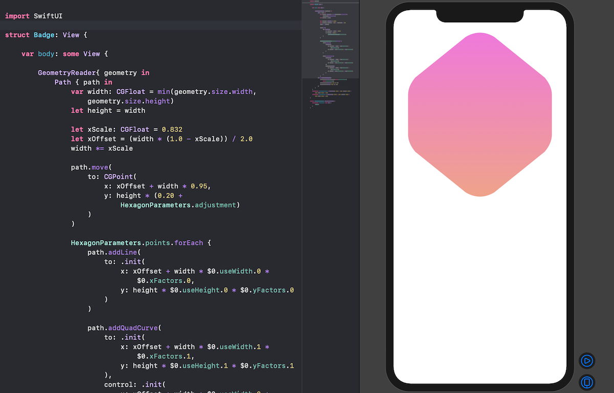
色の指定は,0~255の範囲で指定したいがために, red: 239.0 / 255, のような書き方をしていますが,公式でこう書くくらいなら最初からそう定義すれば良かったのでは?と私は思いますが,まあ良いでしょう.
今回の加筆コードでグラデーションの塗りつぶしの仕方もわかりましたね.
最後に,最後にアスペクト比を横幅に合わせ,ビューにフィットするようにします.
1 2 3 4 5 6 7 8 9 10 11 12 13 14 15 16 17 18 19 20 21 22 23 24 25 26 27 28 29 30 31 32 33 34 35 36 37 38 39 40 41 42 43 44 45 46 47 48 49 50 | struct Badge: View { var body: some View { GeometryReader{ geometry in Path { path in var width: CGFloat = min(geometry.size.width, geometry.size.height) let height = width let xScale: CGFloat = 0.832 let xOffset = (width * (1.0 - xScale)) / 2.0 width *= xScale path.move( to: CGPoint( x: xOffset + width * 0.95, y: height * (0.20 + HexagonParameters.adjustment) ) ) HexagonParameters.points.forEach { path.addLine( to: .init( x: xOffset + width * $0.useWidth.0 * $0.xFactors.0, y: height * $0.useHeight.0 * $0.yFactors.0 ) ) path.addQuadCurve( to: .init( x: xOffset + width * $0.useWidth.1 * $0.xFactors.1, y: height * $0.useHeight.1 * $0.yFactors.1 ), control: .init( x: xOffset + width * $0.useWidth.2 * $0.xFactors.2, y: height * $0.useHeight.2 * $0.yFactors.2 ) ) } }.fill(LinearGradient( gradient: .init(colors: [Self.gradientStart, Self.gradientEnd]), startPoint: .init(x: 0.5, y: 0), endPoint: .init(x: 0.5, y: 0.6) )) .aspectRatio(1, contentMode: .fit) } } static let gradientStart = Color(red: 239.0 / 255, green: 120.0 / 255, blue: 221.0 / 255) static let gradientEnd = Color(red: 239.0 / 255, green: 172.0 / 255, blue: 120.0 / 255) } |
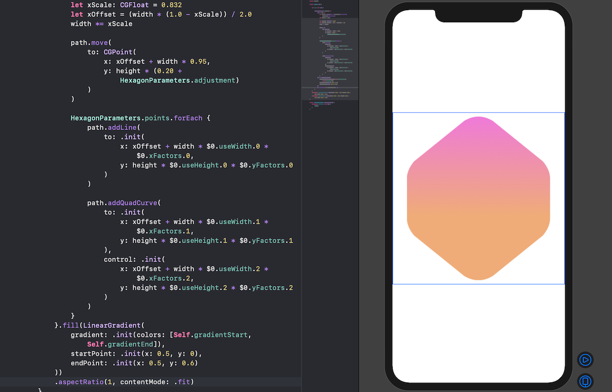
良い感じですね.
Step 4. バッジシンボルを描く
次に,先ほどの背景の上に描くシンボルを描画していきますが,ここでは一つの図形を複製し,回転などの操作を組み合わせ一つのバッジを描くことをやってみます.
まずはその図形を作りましょう.
この図形については,コードは複雑に見えますがやっていることはシンプルですので,詳細は省きます.
ここはコピペでも構わないです.
1 2 3 4 5 6 7 8 9 10 11 12 13 14 15 16 17 18 19 20 21 22 23 24 25 26 27 28 29 30 31 32 | import SwiftUI struct BadgeSymbol: View { var body: some View { GeometryReader { geometry in Path { path in let width = min(geometry.size.width, geometry.size.height) let height = width * 0.75 let spacing = width * 0.03 let middle = width / 2 let topWidth = 0.226 * width let topHeight = 0.488 * height path.addLines([ CGPoint(x: middle, y: spacing), CGPoint(x: middle - topWidth, y: topHeight - spacing), CGPoint(x: middle, y: topHeight / 2 + spacing), CGPoint(x: middle + topWidth, y: topHeight - spacing), CGPoint(x: middle, y: spacing) ]) } } } } struct BadgeSymbol_Previews: PreviewProvider { static var previews: some View { BadgeSymbol() } } |
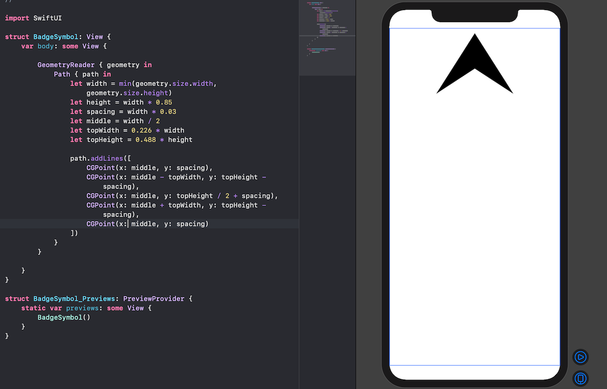 (上図では let height = width * 0.85 となっていますが,本当は let height = width * 0.75 です.筆者は途中で気づいて修正しますので,みなさまは間違わないように... )
かなり決め打ちな値が多いですが,ここでそれらの数字を適当に変えてみて,描画にどのような変化があるか確かめてみると良いでしょう.
1 2 3 4 5 6 7 8 9 10 11 12 13 14 15 16 17 18 19 20 21 22 23 24 25 26 27 28 29 30 31 32 33 | struct BadgeSymbol: View { var body: some View { GeometryReader { geometry in Path { path in let width = min(geometry.size.width, geometry.size.height) let height = width * 0.75 let spacing = width * 0.03 let middle = width / 2 let topWidth = 0.226 * width let topHeight = 0.488 * height path.addLines([ CGPoint(x: middle, y: spacing), CGPoint(x: middle - topWidth, y: topHeight - spacing), CGPoint(x: middle, y: topHeight / 2 + spacing), CGPoint(x: middle + topWidth, y: topHeight - spacing), CGPoint(x: middle, y: spacing) ]) path.move(to: CGPoint(x: middle, y: topHeight / 2 + spacing * 3)) path.addLines([ CGPoint(x: middle - topWidth, y: topHeight + spacing), CGPoint(x: spacing, y: height - spacing), CGPoint(x: width - spacing, y: height - spacing), CGPoint(x: middle + topWidth, y: topHeight + spacing), CGPoint(x: middle, y: topHeight / 2 + spacing * 3) ]) } } } } |
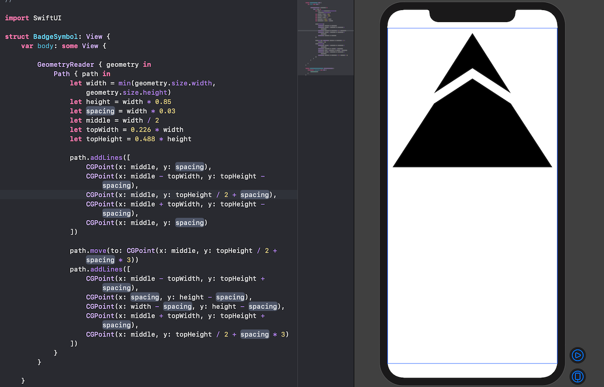
1 2 3 4 5 6 7 8 9 10 11 12 13 14 15 16 17 18 19 20 21 22 23 24 25 26 27 28 29 30 31 32 33 34 35 36 | struct BadgeSymbol: View { static let symbolColor = Color(red: 79.0 / 255, green: 79.0 / 255, blue: 191.0 / 255) var body: some View { GeometryReader { geometry in Path { path in let width = min(geometry.size.width, geometry.size.height) let height = width * 0.75 let spacing = width * 0.03 let middle = width / 2 let topWidth = 0.226 * width let topHeight = 0.488 * height path.addLines([ CGPoint(x: middle, y: spacing), CGPoint(x: middle - topWidth, y: topHeight - spacing), CGPoint(x: middle, y: topHeight / 2 + spacing), CGPoint(x: middle + topWidth, y: topHeight - spacing), CGPoint(x: middle, y: spacing) ]) path.move(to: CGPoint(x: middle, y: topHeight / 2 + spacing * 3)) path.addLines([ CGPoint(x: middle - topWidth, y: topHeight + spacing), CGPoint(x: spacing, y: height - spacing), CGPoint(x: width - spacing, y: height - spacing), CGPoint(x: middle + topWidth, y: topHeight + spacing), CGPoint(x: middle, y: topHeight / 2 + spacing * 3) ]) } .fill(Self.symbolColor) } } } |
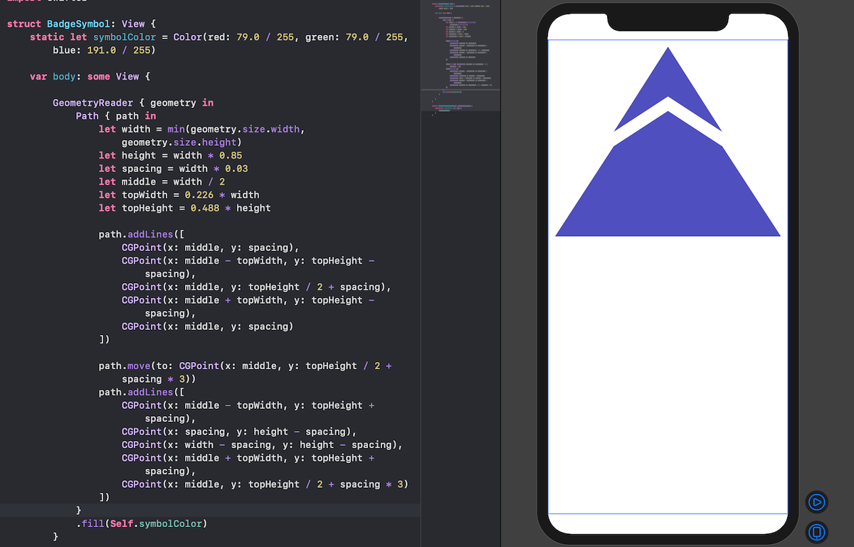
これで,元となる図は完成です.
これを組み合わせていきましょう.
Step 5. バッジの組み合わせ
まず,わかりやすくするためにStep 2で作成した「Badge.swift」を「BadgeBackground.swift」に名前を変更してください.
その次に,BadgeSymbolの回転操作を簡単にするために「RotatedBadgeSymbol.swift」を作成します.
1 2 3 4 5 6 7 8 9 10 11 12 13 14 15 16 17 18 | import SwiftUI struct RotatedBadgeSymbol: View { let angle: Angle var body: some View { BadgeSymbol() .padding(-60) .rotationEffect(angle, anchor: .bottom) } } struct RotatedBadgeSymbol_Previews: PreviewProvider { static var previews: some View { RotatedBadgeSymbol(angle: .init(degrees: 5)) } } |
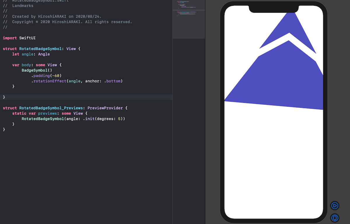
プレビューでは仮で,「5度回転」としています.
その次に,また新たに「Badge.swift」を作成し,ここで先ほど作ったパーツたちを呼び出していきます.
まずは適当に呼び出してみます.
1 2 3 4 5 6 7 8 9 10 11 12 13 14 15 16 17 18 19 20 21 22 | import SwiftUI struct Badge: View { var badgeSymbols: some View { RotatedBadgeSymbol(angle: .init(degrees: 0)) .opacity(0.5) // 透過度 } var body: some View { ZStack { BadgeBackground() self.badgeSymbols } } } struct Badge_Previews: PreviewProvider { static var previews: some View { Badge() } } |
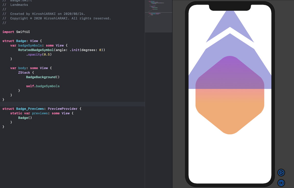
バッジシンボルを,また GeometryReader { } を使ってサイズ調整しましょう.
1 2 3 4 5 6 7 8 9 10 11 12 13 14 15 16 17 18 | struct Badge: View { var badgeSymbols: some View { RotatedBadgeSymbol(angle: .init(degrees: 0)) .opacity(0.5) } var body: some View { ZStack { BadgeBackground() GeometryReader { geometry in self.badgeSymbols .scaleEffect(1.0 / 4.0, anchor: .top) .position(x: geometry.size.width / 2.0, y: (3.0 / 4.0) * geometry.size.height) } } } } |
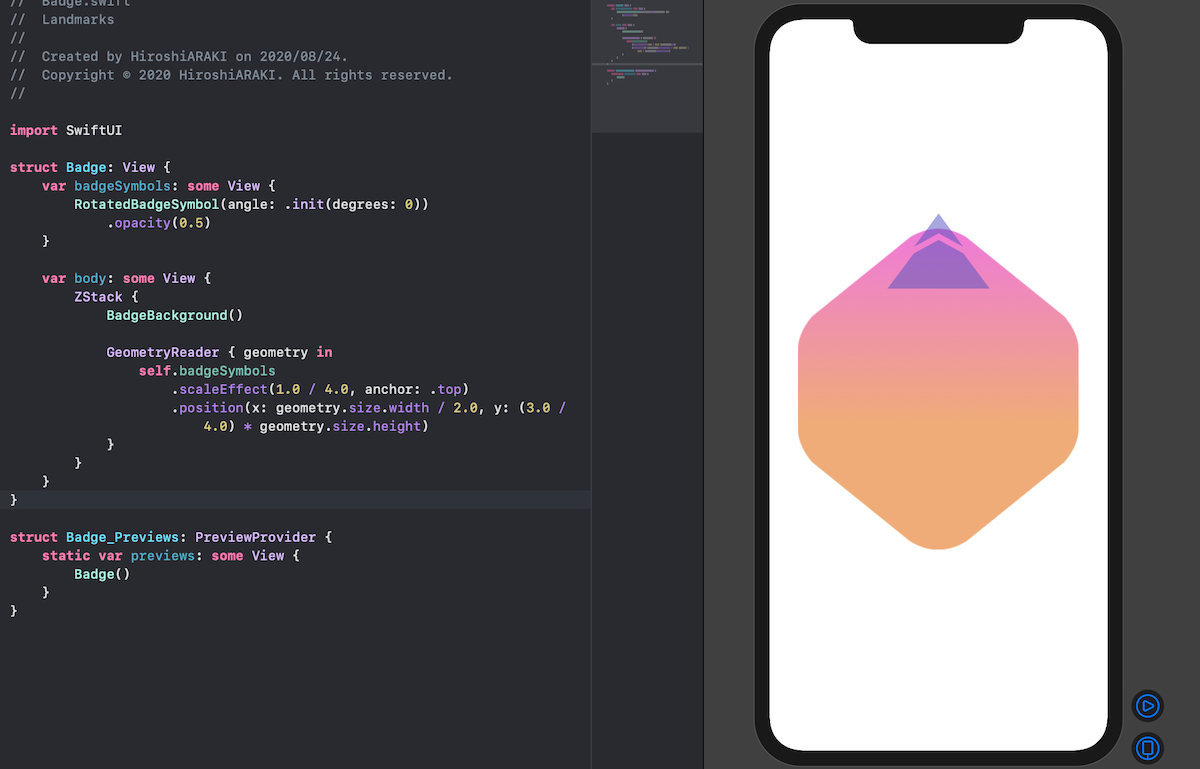 (ここで,先ほどの定数が違うと気がつきました.汗)
最後に,シンボルを量産しましょう.
今回は8分割にして円形に描画してみます.
1 2 3 4 5 6 7 8 9 10 11 12 13 14 15 16 17 18 19 20 21 22 23 24 25 | struct Badge: View { static let rotationCount = 8 var badgeSymbols: some View { ForEach(0..<Badge.rotationCount) { i in RotatedBadgeSymbol( angle: .degrees(Double(i) / Double(Badge.rotationCount)) * 360.0 ) } .opacity(0.5) } var body: some View { ZStack { BadgeBackground() GeometryReader { geometry in self.badgeSymbols .scaleEffect(1.0 / 4.0, anchor: .top) .position(x: geometry.size.width / 2.0, y: (3.0 / 4.0) * geometry.size.height) } } .scaledToFit() } } |
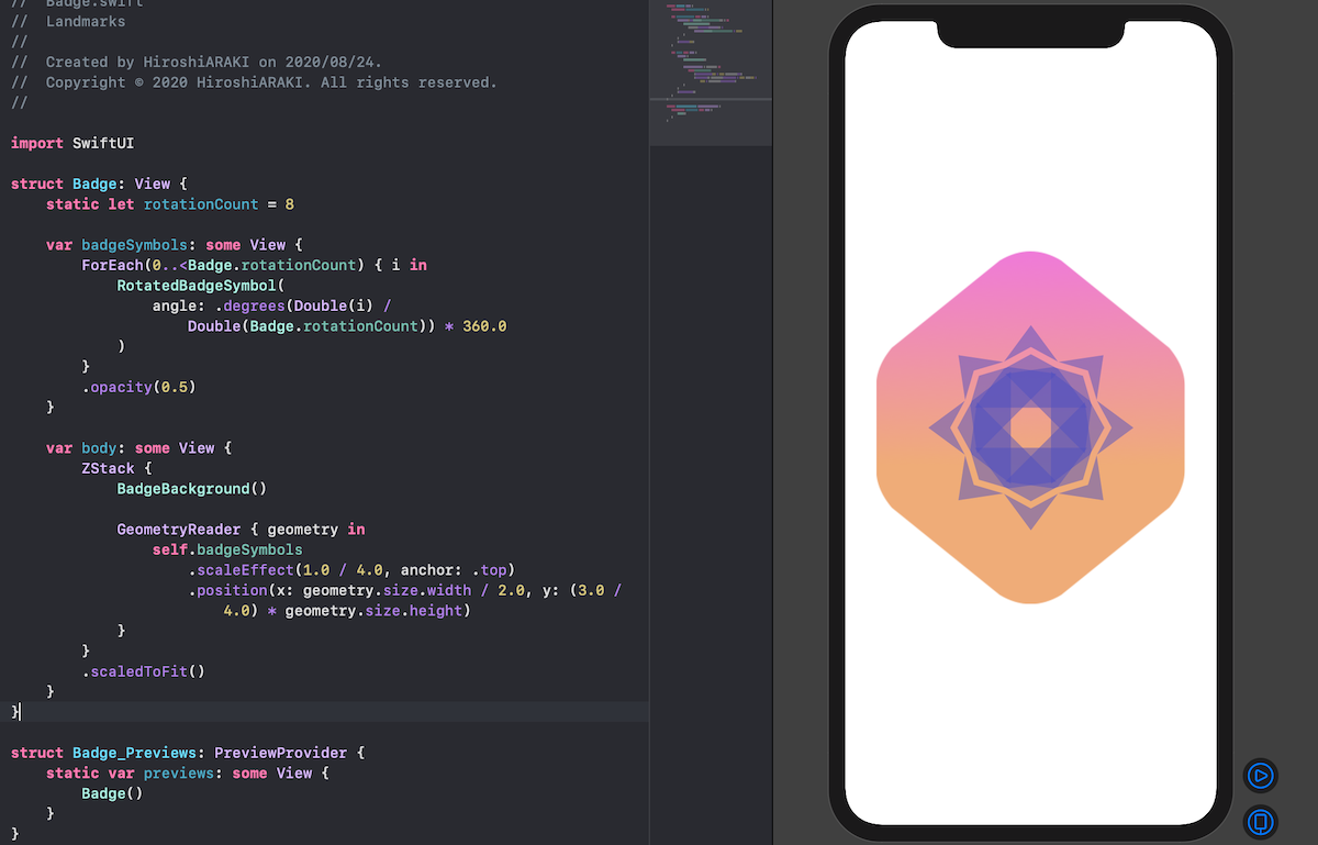
これでバッジ完成です!
このバッジはまたいずれアプリで使用するのでこのままにしておいてください!
第4回:おわりに
今回は,図形の描画について紹介しました.
前回までと毛色が変わり,困惑した方もいるかもしれませんが第6回あたりで合流しますので,引き続き頑張っていきましょう!
さて次回は,「アニメーション」の実装についてです.

